
How to Calibrate Alignment Systems in Your Shop
How to Calibrate Alignment Systems in Your Shop
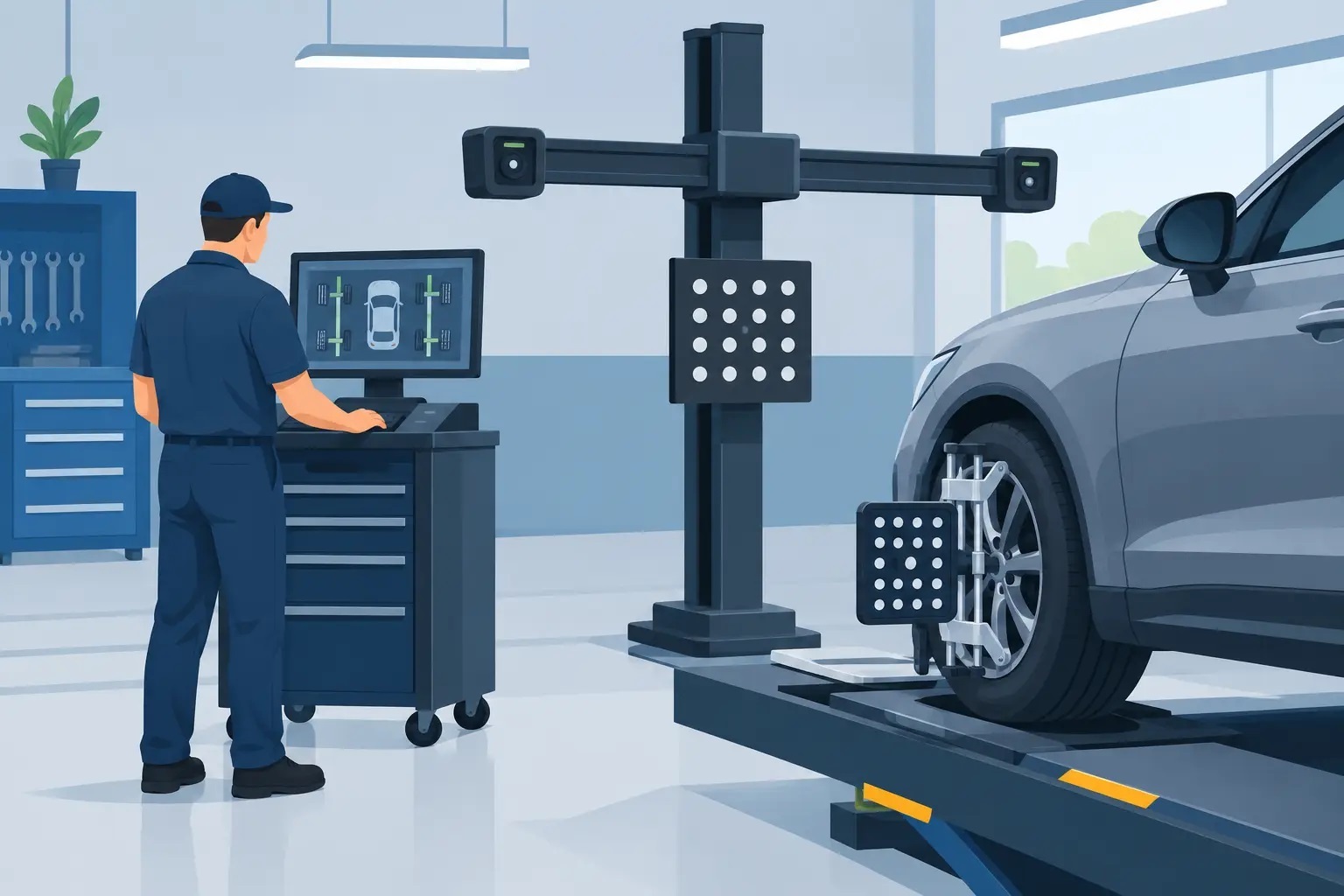
A modern aligner can show measurements to a hundredth of a degree, but that precision means little if the system is reading a crooked target, an unlevel runway, or a damaged turn plate. Knowing how to calibrate alignment systems is not just a software exercise. It is a controlled check of the aligner, the lift or alignment rack, the targets or sensors, and the shop environment that supports them.
For a busy repair shop, calibration protects more than alignment accuracy. It reduces comebacks, prevents unnecessary parts sales based on bad readings, and gives technicians confidence when a customer questions a printout. The exact process varies by manufacturer and model, so the machine's current service documentation always takes priority. The practical workflow below applies to most camera-based and sensor-based wheel alignment systems used in professional shops.
Start by Separating Calibration From Setup
Technicians often use the word calibration to describe any time an aligner is prepared for a vehicle. That can create problems. Vehicle compensation, target mounting, ride-height entry, and steering-angle sensor resets are part of a normal alignment procedure. They do not necessarily calibrate the machine itself.
System calibration confirms that the aligner's reference points are accurate. Depending on the unit, this may include camera geometry, sensor angles, crossbar position, target recognition, turn-plate zero, or the relationship between the aligner and the lift runways. A machine can complete a vehicle compensation routine perfectly and still produce questionable results if its camera beam or fixture calibration is off.
Before taking anything apart or changing values in the software, identify the type of system in the bay. A fixed-tower camera aligner, a mobile camera console, a conventional sensor-head aligner, and a 3D target system do not use the same calibration method. Use the manufacturer-specified calibration bar, target board, fixture, or gauge when required. Improvised substitutes are a fast way to build error into every alignment.
Prepare the Alignment Bay First
Calibration begins with the floor and rack, not the keyboard. Clear the bay of loose tools, hoses, wheel chocks, and anything that could interfere with camera sight lines or moving plates. Clean the targets, camera lenses, sensor windows, clamps, and reflectors with materials approved by the equipment manufacturer. Brake dust, overspray, fingerprints, and adhesive residue can all affect target recognition.
Lighting matters, particularly with optical and camera-based systems. Avoid direct sunlight across the targets and eliminate glare from open doors, reflective wall panels, or work lights aimed straight at the cameras. A change in lighting does not usually require a full calibration, but poor lighting can look like a calibration issue and waste diagnostic time.
Next, inspect the alignment lift or rack. The runways must be level within the limits specified by the lift and aligner manufacturers. Verify that the lift is fully down on its mechanical stops or locked at its designated alignment height. Do not calibrate while the lift is suspended on hydraulic pressure or positioned unevenly on safety locks.
Check the turn plates and rear slip plates as well. Turn plates should rotate freely, lock securely when needed, and return to their indicated zero position. Slip plates must slide without binding and be locked or unlocked according to the procedure being performed. Bent plates, seized bearings, broken lock pins, and missing bridge covers can create false toe or caster readings even when the aligner itself is properly calibrated.
Inspect the Hardware Before Running Software Calibration
A calibration routine cannot correct damaged physical components. Examine the camera tower, beam, cabinet, or sensor stand for signs of impact. A tower that has been hit by a vehicle door, a tire, or a rolling tool chest may be visibly straight while its internal geometry is no longer within specification.
Look closely at target clamps and sensor heads. Clamps should grip the wheel securely without bent fingers, worn threads, or excessive play. A loose clamp can shift during rolling compensation and mimic a wheel or suspension problem. Check target panels for cracks, warped surfaces, missing reflective material, faded patterns, or labels that have been covered with tape or marker ink.
For wired sensor-head equipment, inspect cables and connectors. Pinched cords, damaged strain reliefs, and intermittent plugs can cause readings to drop out or drift. For wireless systems, verify battery condition and charging contacts before assuming a sensor has failed. Low voltage can produce inconsistent communication and lead a technician toward the wrong diagnosis.
If the system includes a dedicated calibration fixture, confirm it is complete, clean, and stored where it cannot be bent or dropped. These fixtures are measuring tools, not general shop hardware. A calibration bar that has been damaged should be replaced or checked by an authorized service provider before it is used.
How to Calibrate Alignment Systems Step by Step
Once the bay and hardware are ready, follow the calibration function in the aligner's software. Most professional systems guide the operator through the sequence, but the order of operations still matters.
Confirm Software, Specifications, and Service Status
Power up the aligner and allow it to complete its startup check. Confirm that the software is current enough to support the system hardware and the vehicle coverage your shop services. Software updates do not replace physical calibration, but outdated software can create other measurement and workflow issues.
Review any service alerts, calibration-due notices, camera communication warnings, or sensor battery messages. If the system reports a component fault, correct that fault before proceeding. Calibrating around an active error can mask the cause temporarily without restoring dependable measurements.
Position the Calibration Fixture Exactly
Install or position the manufacturer-approved fixture at the specified location on the alignment rack. This is usually measured from the camera tower, runway centerline, or front turn plates. Follow the required orientation and height. Even a small placement error can alter the reference geometry the machine is trying to establish.
Do not assume the fixture should be centered visually. Use the dimensions and locator points provided in the equipment instructions. On some systems, the fixture is moved through several positions so the cameras can calculate angle and distance. On others, it remains stationary while the cameras or sensor heads are adjusted.
Keep people, vehicles, and moving equipment out of the camera path during this process. A technician walking between a camera and its target at the wrong moment may interrupt the reading and force the routine to restart.
Run the Guided Calibration Routine
Select the correct calibration menu for your equipment model, then complete each prompt without skipping steps. The software may ask you to level a bar, rotate a sensor, move a target, lock turn plates, or verify a known dimension. Record any before-and-after values if the system provides them.
Avoid manually entering correction values unless the manufacturer specifically directs it. Most modern aligners calculate calibration offsets automatically from the fixture readings. Manual changes made to get a passing screen can leave the equipment less accurate than it was before service.
If the routine fails, do not repeat it several times hoping for a different result. Stop and inspect the fixture placement, target cleanliness, cable connections, ambient lighting, and tower condition. Repeated failures commonly point to a hardware issue, an unlevel rack, or a damaged calibration accessory.
Verify With a Controlled Test
A successful calibration screen is not the final check. Run a controlled verification using the manufacturer's recommended test method. This may involve mounting targets on a known-good vehicle, checking a calibration plate, or comparing repeat readings after the targets are removed and remounted.
The key is repeatability. If toe, camber, or thrust angle changes substantially when nothing on the vehicle has changed, investigate clamp seating, wheel runout compensation, target condition, and plate movement. Do not release an aligner back to production based only on one acceptable reading.
For shops that perform high-volume alignment work, save or print the verification result with the calibration date, technician name, equipment serial number, and any service performed. This creates a useful baseline when a problem develops later.
When to Recalibrate Your Alignment Machine
Every manufacturer sets its own preventive-maintenance schedule, and that interval should be your starting point. In actual shop use, recalibration is also warranted after a camera tower is bumped, a sensor head is dropped, targets are replaced, the rack is moved, or turn plates and slip plates are repaired.
Recheck the system after major changes to the bay, including concrete work, lift installation, runway shimming, or electrical service that required equipment relocation. It also makes sense to schedule calibration when technicians report inconsistent measurements, unusual compensation results, or repeat alignment comebacks that cannot be traced to the vehicle.
A light-duty alignment bay that handles a few passenger vehicles per day may need less frequent attention than a dealership or tire shop running alignments continuously. Heavy-duty alignment equipment has its own challenges, including larger runways, higher-capacity turn plates, and greater opportunity for fixture damage. Usage and working conditions matter as much as the calendar.
Protect Accuracy Between Calibration Intervals
The best way to reduce calibration downtime is to treat the aligner as precision equipment. Keep targets in their holders, protect camera towers from traffic, store fixtures separately from general hand tools, and train every technician on proper clamp installation. A clean, organized alignment bay also makes it easier to see when a plate is binding or a target has been damaged.
When an alignment result does not match tire wear, steering feel, or a previous measurement, question the process before selling parts. Check tire pressure, wheel condition, vehicle loading, ride height, clamp fit, and compensation procedure. The aligner may be right, but it needs a sound setup and verified calibration to prove it.
An alignment system earns its place in the shop by producing measurements technicians can trust. Keep the rack level, protect the targets and fixtures, follow the equipment maker's calibration procedure, and verify the result before the next vehicle rolls into the bay.
Recent Posts
-
How to Calibrate Alignment Systems in Your Shop
How to Calibrate Alignment Systems in Your Shop A modern aligner can show measurements to a hundred …13th Oct 2026 -
EV Servicing Equipment for Productive Shops
EV Servicing Equipment for Productive Shops A battery-electric vehicle may come in for the same tir …11th Oct 2026 -
A Practical Guide to Vehicle Lift Adapters
A Practical Guide to Vehicle Lift Adapters A lift can have the right rated capacity and still be th …9th Oct 2026